- Definition
- Simulation
- Synchronization Errors
- IQ imbalance estimation in MIMO-OFDM systems
- IQ imbalance compensation
- IQ imbalance estimation
- References
IQ imbalance is a performance-limiting issue in the design of direct conversion receivers, also known as zero intermediate frequency (IF) or homodyne receivers. Such a design translates the received radio frequency (RF, or passband) signal directly from the carrier frequency (fc) to baseband using only one mixing stage. The traditional heterodyne receiver structure needs an intermediate-frequency (IF) stage between the RF and baseband signals. The direct conversion receiver structure does not have an IF stage, and does not need an image rejection filter. Due to the lower component count, it is easier to integrate. However, a direct-conversion RF front-end suffers from two major drawbacks: one is IQ imbalance and the other is DC offset. When designing a homodyne receiver, control of IQ imbalance is necessary to limit signal demodulation error.
IQ imbalances occur due to mismatches between the parallel sections of the receiver chain dealing with the in-phase (I) and quadrature (Q) signal paths. The local oscillator (LO) generates a sinewave, and a copy of that sinewave that is delayed by 90 degrees. When the direct LO output is mixed with the original signal, this produces the I signal, whereas when the delayed LO output is mixed with the original signal, that produces the Q signal. In the analog domain, the delay is never exactly 90 degrees. Similarly, analog gain is never perfectly matched for each of the signal paths.
Definition
A direct conversion receiver uses two quadrature sinusoidal signals to perform the so-called quadrature down conversion. This process requires shifting the local oscillator (LO) signal by 90 degrees to produce a quadrature sinusoidal component. When mismatches exist between the gain and phase of the two sinusoidal signals and/or along the two branches of down-conversion mixers, amplifiers, and low-pass filters, the quadrature baseband signals will be corrupted.
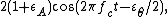
Suppose the received passband signal is identical to the transmitted signal and is given by

Assume that the gain error is  dB and the phase error is
  degrees. Then we can model such imbalance using mismatched local oscillator output signals.

Multiplying the passband signal by the two LO signals and passing through a pair of low-pass filters, one obtains the demodulated baseband signals as


The above equations clearly indicate that IQ imbalance causes interference between the I and Q baseband signals.
To analyze IQ imbalance in the frequency domain, above equation can be rewritten as

where  denotes the complex conjugate. In an OFDM system, the baseband signal consists of several subcarriers. Complex-conjugating the baseband signal of the kth subcarrier carrying data
  is identical to carrying
  on the (-k)th subcarrier:

where  is the subcarrier spacing.
Equivalently, the received baseband OFDM signal under the IQ imbalance effect is given by
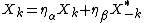
In conclusion, besides a complex gain imposed on the current sub carrier data Xk, IQ imbalance also introduces ICI from the mirror subcarrier. The ICI term makes OFDM receivers very sensitive to the IQ imbalance effect. To solve this problem, the designer can request a stringent specification of the matching of the two branches in the frond-end or compensate for the imbalance in the baseband receiver.
Simulation
IQ imbalance can be simulated by computing the gain and phase imbalance and applying them to the baseband signal by means of several real multipliers and adders.
Synchronization Errors
The time-domain baseband Signals with IQ imbalance can be represented by

Note that  and
and  can be assumed to be time-invariant and frequency-invariant, meaning that they are constant over several sub carriers and symbols. With this property, multiple OFDM subcarriers and symbols can be used to jointly estimate and to increase the accuracy. Transforming to the frequency domain, we have the frequency-domain OFDM signals under the influence of IQ imbalance given by

Note that the second term represents interference coming from the mirrored subcarrier 
IQ imbalance estimation in MIMO-OFDM systems
In MIMO-OFDM systems, each RF channel has its own down-converting circuit. Therefore, the IQ imbalance for each RF channel is independent of those for the other RF channels.
Considering a 2 x 2 MIMO system as an example, the received frequency-domain signal is given by
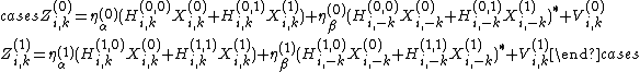
where  and
and  are the IQ imbalance coefficients of the qth receive RF channel.
Estimation of and is the same for each RF channel. Therefore, we take the first RF channel as an example. The received signals at the pilot subcarriers of the first RF channel are stacked into a vector  ,
,
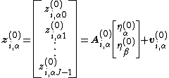
where  is the
  matrix
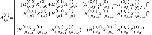
Clearly, the above formula is similar to that of the SISO case and can be solved using the LS method. Moreover, the estimation complexity can be reduced by using fewer pilot subcarriers in the estimation.
IQ imbalance compensation
The IQ imbalance can be compensated in either the time domain or the frequency domain. In the time domain, the compensated signal Zm in the current mth sample point is given by
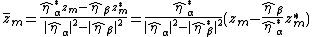
We can see that, by using the ratio  to mitigate the IQ imbalance, there is a loss factor
  . When the noise is added before the IQ imbalance, the SNR remains the same, because both noise and signal suffer this loss. However, if the noise is added after IQ imbalance, the effective SNR degrades. In this case, and , respectively, should be computed.
Compared with the time-domain approach, compensating in the frequency domain is more complicated because the mirrored subcarrier is needed. The frequency domain compensated signal at the ith symbol and the kth subcarrier

Nevertheless, in reality, the time-domain compensation is less preferred because it introduces larger latency between IQ imbalance estimation and compensation.
IQ imbalance estimation
Frequency-domain OFDM signals under the influence of IQ imbalance is given by
the IQ imbalance coefficients and are mixed with the channel frequency responses, making both the IQ imbalance estimation and channel estimation difficult.
In the first half of the training sequence, only sub carriers ranging from 1 to N/2 - 1 transmit pilot symbols; the remaining subcarriers are not used. In the second half, the sub carriers from -1 to -N/2 are used for pilot transmission. Such a training scheme easily decouples the IQ imbalance and the channel frequency response. Assuming the value of the pilot symbols is + 1, the received signals at subcarriers from 1 to N/2 - 1 are given by
 ,
,
while the received signals at the mirrored sub carriers take the form

From the two sets of received signals, the ratio  can be easily estimated by
  . The second half of the training sequence can be used in a similar way. Furthermore, the accuracy of this ratio estimation can be improved by averaging over several training symbols and several sub carriers. Although the IQ imbalance estimation using this training symbol is simple, this method suffers from low spectrum efficiency, as quite a few OFDM symbols must be reserved for training. Note that, when the thermal noise is added before the IQ imbalance, the ratio is sufficient to compensate the IQ imbalance. However, when the noise is added after the IQ imbalance, compensation using only can degrade the ensuing demodulation performance.
References
- M. Valkama, M. Renfors, and V. Koivunen, 2001 . "Advanced methods for I/Q imbalance compensation in communication receivers," IEEE Transactions on Signal ProceSSing, 49, 2335-2344
- J. Tubbax, B . Come, L. V. der Perre, S. Donnay, M. Engels, H. D. Man, and M. Moonen, 2005. " Compensation of IQ imbalance and phase noise in OFDM systems," IEEE Transactions on Wreless Communications, 4, 872-877.
- T.D Chiueh, PY Tsai, IW L, "Baseband Receiver Design for Wireless MIMO_OFDM Communications 2nd"
- 1956–57 The Citadel Bulldogs basketball team
- 1956–57 The Citadel Bulldogs men's basketball team
- 1956–57 Tunisian Ligue Professionnelle 1
- 1956–57 Western Football League
- 1956–57 West Ham United F.C. season
- 1956–57 William & Mary Indians men's basketball team
- 1956–57 York City F.C. season
- 1956–57 Yugoslav Cup
- 1956–57 Yugoslav Ice Hockey League season
- 1956–59 Nordic Football Championship
- 1957-58 Birmingham City F.C. season
- 1957-58 Boston Celtics season
- 1957-58 British Home Championship
- 1957-58 Bulgarian Hockey League season
- 1957-58 Colchester United F.C. season
- 1957-58 Czechoslovak Extraliga season
- 1957-58 Detroit Pistons season
- 1957-58 Division 3
- 1957-58 Eredivisie
- 1957-58 Georgetown Hoyas men's basketball team
- 1957-58 Hong Kong First Division League
- 1957-58 Huddersfield Town F.C. season
- 1957-58 IHL season
- 1957-58 in Belgian football
- 1957-58 Irish League